Introduction
Every smartphone, car dashboard, and smart home device relies on an invisible workforce — microcontrollers. These tiny chips power nearly everything around us, yet most people never realize they're there. If you've ever wondered how your fitness tracker counts steps, how a traffic signal switches on cue, or how your TV remote communicates wirelessly with your screen, the answer is microcontroller programming.
Microcontroller programming is the process of writing, compiling, and uploading code that tells a microcontroller exactly what to do — from blinking an LED to reading sensor data and controlling motors. For students, hobbyists, and curious makers aged 13 and above, this skill opens doors to robotics, IoT, smart devices, and embedded systems.
With over 31 billion microcontroller units shipped globally in 2021 alone, it's a skill tied to an industry projected to reach $62.74 billion by 2031. This guide walks you through the fundamentals — what microcontrollers are, how to write your first program, which platform to choose, and the common mistakes worth avoiding early on.
Key Takeaways
- Microcontroller programming means writing code, compiling it to machine language, and uploading it to a chip to control hardware
- C/C++ dominates professional embedded work; MicroPython is the friendlier on-ramp for beginners
- Start with Arduino — 30 million users worldwide and nearly 9,000 community libraries make it the most beginner-ready platform
- The core workflow — write, compile, upload — stays consistent across platforms; only the tools change
- Hands-on building beats theory every time; start simple, test incrementally, read datasheets
What Is Microcontroller Programming and Why It Matters
A microcontroller is a compact integrated circuit that combines a processor, memory, and I/O peripherals on a single chip — a tiny computer designed to perform specific, repeated tasks. Unlike a general-purpose microprocessor (like the CPU in your laptop), which requires external RAM, storage, and peripheral chips, a microcontroller integrates everything it needs into one package. This makes it self-contained, cost-effective, and ideal for embedded applications.
Microcontroller programming gives the chip its "instructions." Without code, a microcontroller does nothing. Your program determines how it responds to inputs (button presses, sensor readings, wireless signals) and what outputs it controls (LEDs, motors, displays, communication protocols). Every action the chip performs — reading temperature, adjusting motor speed, sending data over Wi-Fi — happens because someone wrote code to make it happen.
Approximately 31.2 billion microcontroller units were shipped globally in 2021 — a 13% jump from 2020. A typical car contains 25-35 microcontrollers; luxury models house up to 70. These chips aren't exotic — they're everywhere you look:
- Automotive: engine timing, airbag deployment, climate control, infotainment
- Home appliances: washing machines, microwaves, smart thermostats, security cameras
- Healthcare: patient monitors, infusion pumps, diagnostic equipment

Once you understand how to program a microcontroller, you can read, build, and modify the systems running most of the physical world around you.
How Microcontroller Programming Works
Microcontroller programming follows a three-step workflow: write, compile, upload. You write human-readable source code on your computer, a compiler translates that code into machine-readable binary instructions, and a programmer tool or USB connection uploads the compiled file to the microcontroller's flash memory. Once uploaded, the chip runs the program independently every time it powers on.
What Goes In
You write source code files containing your logic: which pins to read, which to control, how to respond to sensor data, and what outputs to drive. Common file types include:
.c— C source files.cpp— C++ source files.ino— Arduino sketches
You also include header files that define hardware configurations and any required libraries (pre-written modules for common tasks like controlling displays or reading sensors).
One important constraint: code written for an AVR-based Arduino won't run on an ARM Cortex-M STM32 without modification. Each microcontroller family has its own memory layout, peripheral registers, and instruction set — so you always write for a specific target.
What Happens During Compilation
The compiler checks your code for syntax errors, optimizes it for efficiency, and converts it to a binary file (often called a .hex file) specific to the target chip. The compiler must match the microcontroller family:
- avr-gcc for AVR chips (used in Arduino Uno, Nano)
- MPLAB XC8 for 8-bit PIC microcontrollers
- STM32CubeIDE for STM32 ARM-based chips
If your code has errors — missing semicolons, undefined variables, incorrect function calls — compilation fails, and you must fix the issues before proceeding.
How the Compiled File Is Uploaded
The binary file is flashed into the microcontroller's non-volatile flash memory using a physical connection. There are two common scenarios:
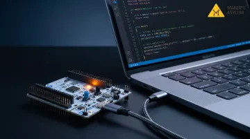
Development boards like Arduino have a built-in USB-to-serial bootloader. You plug in a USB cable, click Upload in the IDE, and the bootloader handles the rest. The bootloader occupies 1-2 KB of flash memory and listens for incoming data after reset. The entire process takes seconds.
Bare microcontrollers (chips not mounted on a development board) require a dedicated hardware programmer like USBasp or AVRISP. These programmers connect to specific pins on the chip — MOSI, MISO, SCK, RST — using SPI (Serial Peripheral Interface) protocol. This method gives you more control but requires understanding pinouts and wiring.
How the Program Lives on the Chip
The program is stored in the chip's flash memory, which retains data even when power is removed. Every time the microcontroller powers on or resets, the CPU fetches the first instruction from the reset vector address in flash and starts executing from there — usually landing in an infinite loop (while(1) in C or loop() in Arduino). There's no "program finished" state. The chip just keeps running, reading inputs and driving outputs, until it loses power or resets.
Step 1: Write Your Code
Source code for microcontrollers is typically written in C or C++ (Arduino uses C++ with simplified syntax). You need to understand three fundamental building blocks:
- Variables store data: sensor readings, pin states, counters, thresholds — declared with a type (
int,float,char) and a name - Control flow handles program logic —
if/elsemakes decisions (if temperature exceeds 30°C, turn on fan), whileforandwhileloops repeat actions (blink LED 10 times, read sensor every second) - Functions are reusable code blocks you define once and call wherever needed, keeping your program clean and organised
These building blocks work together inside the defining feature of embedded code: the infinite main loop. Unlike desktop software that runs a task and exits, microcontroller programs loop forever:
void setup() {
  // Initialize pins, peripherals, sensors
}

void loop() {
  // Read inputs, execute logic, control outputs
  // This runs continuously
}
Every microcontroller program you write will follow this structure — setup runs once, then loop takes over indefinitely.
Step 2: Compile the Code
Compiling translates your human-readable source code into machine code (binary/hex) that the microcontroller's CPU can execute. The compiler is platform-specific:
- Arduino IDE compiles automatically when you click Upload
- avr-gcc compiles bare-metal AVR code
- MPLAB XC8 compiles for PIC microcontrollers
- STM32CubeIDE compiles for STM32 ARM chips
The compiler also checks your code for syntax errors — things like missing semicolons, typos, or undefined functions — and optimizes it to reduce size and improve speed. If it finds any issues, it halts and flags them; you'll need to resolve every error before the upload can proceed.
Common errors beginners run into:
- Missing or incorrectly installed libraries
- Incorrect variable types for the operation being performed
- Mismatched function arguments (wrong number or type)
Step 3: Upload to the Microcontroller
The compiled binary is flashed into the chip's program memory using a physical connection. How you upload depends on your hardware:
Development boards like Arduino Uno have a built-in bootloader that makes uploading simple. Connect the board via USB, click Upload in the IDE, and the bootloader receives the binary over serial and writes it to flash. This is beginner-friendly and fast.
Bare microcontrollers require a hardware programmer. The setup varies by chip family:
- AVR chips: Use USBasp connected to MOSI, MISO, SCK, and RST pins via SPI
- STM32 chips: Use ST-Link via JTAG or SWD pins
- Both: Wire the programmer correctly, set fuses (configuration bits), then flash using command-line tools or IDE integration
Once uploaded, the program runs immediately from flash memory. The microcontroller executes the code every time it powers on, starting from the reset vector and entering the main loop.
Choosing Your First Platform and Language
Start with Arduino. It's the most beginner-friendly entry point by a wide margin. Arduino claims over 30 million users worldwide, with 8,754 community libraries and thousands of tutorials. The Arduino IDE abstracts low-level setup, handles compilation and upload automatically, and uses beginner-friendly syntax on top of C/C++. The Arduino Uno uses the ATmega328P, a real AVR microcontroller — the skills you learn transfer directly to bare-metal programming later.
Progression Path
Once comfortable with Arduino (typically after building 5-10 projects), you can move to:
Bare AVR microcontrollers — same chip family as Arduino, but you write code without the Arduino framework. You configure registers directly, set up timers manually, and control peripherals at the hardware level. This teaches you what Arduino abstracts away.
STM32 — ARM Cortex-M, 32-bit, industry-standard chips used in professional embedded systems. More complex than AVR, but far more powerful. STM32CubeIDE and HAL (Hardware Abstraction Layer) libraries are written in C. Most professional firmware is C-based, not C++.
PIC — widely used in industrial and commercial applications. MPLAB XC8 compiler supports all 8-bit PIC and AVR microcontrollers. PIC is less beginner-friendly than Arduino but common in legacy systems.
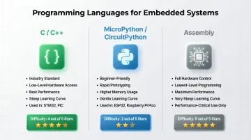
Language Choices
C/C++ is the industry standard. C dominates professional embedded work due to low-level hardware access, efficiency, and portability. Arduino uses C++ with simplified libraries, but STM32 HAL and PIC XC8 are C-centric. If you want a career in embedded systems, learn C.
Python via MicroPython or CircuitPython is approachable for beginners. MicroPython fits into 256 KB of code space and 16 KB of RAM, running on platforms like ESP32, STM32, and Raspberry Pi Pico. CircuitPython supports over 600 boards. Python is slower and uses more memory than C, but it's excellent for rapid prototyping and learning.
Assembly gives full hardware control but has a steep learning curve. It's rarely needed at the beginner stage and only used for performance-critical or size-constrained applications.
ESP32 for IoT
ESP32 bridges beginner and professional domains. It features a dual-core Xtensa LX6 CPU running up to 240 MHz, built-in Wi-Fi 802.11 b/g/n, Bluetooth 4.2/BLE, 520 KB SRAM, and up to 18 ADC channels. You can program it via Arduino IDE, MicroPython, or native ESP-IDF (C-based). It's ideal for IoT projects where connectivity matters.
Working through this progression on your own is doable, but slower. Programs like Maker's Asylum's Innovation School in Goa take a cohort-based approach — participants build actual microcontroller projects with real hardware, get feedback from experienced makers, and move from Arduino basics to more advanced platforms in a structured sequence. For learners who want to go from zero to functional embedded projects quickly, that kind of structured environment makes a real difference.
Key Techniques Every Beginner Should Learn
GPIO (General Purpose Input/Output)
GPIO is the foundation of hardware interaction. Digital pins can be configured as input (reading a button or sensor) or output (driving an LED, relay, or motor signal). Most projects start here. Pin modes (INPUT, OUTPUT), HIGH/LOW states, and register-level control — DDR registers on AVR, TRIS registers on PIC — are the core concepts to get right first.
Interrupts
Instead of continuously checking a pin in a loop (polling), which wastes CPU cycles, interrupts allow the processor to pause its current task when a specific event occurs — a button press, timer overflow, serial data arrival — and execute an Interrupt Service Routine (ISR). ISRs are user-written functions that run when an interrupt fires. This makes code more efficient and responsive, especially in real-time applications.
Communication Protocols
Knowing which protocol a component uses tells you how to wire and program it. The three foundational protocols are:
| Protocol | Wires | Duplex | Topology | Key Feature |
|---|---|---|---|---|
| UART | 2 (TX, RX) | Full-duplex | Point-to-point | No clock line; baud rates must match within ~10% |
| I2C | 2 (SDA, SCL) | Half-duplex | Multi-device bus | Devices addressed by unique 7-bit or 10-bit address |
| SPI | 4 (SCLK, MOSI, MISO, CS) | Full-duplex | Single controller, multiple targets | Dedicated chip-select per target; highest speed |
UART is simple and used for debugging via serial monitor and connecting GPS or Bluetooth modules. I2C allows multiple sensors or displays on one two-wire bus. SPI is faster and used for memory chips, SD cards, and high-speed displays. Source: Texas Instruments and Total Phase.

Timers and PWM
Hardware timers allow precise timing without blocking the main loop. PWM (Pulse Width Modulation) uses timers to control LED brightness, motor speed, and servo position by varying the duty cycle of a square wave signal. PWM rapidly switches an output on and off at a fixed frequency — the percentage of "on" time (duty cycle) determines the result. At 50% duty cycle, an LED runs at half brightness; at 10%, a motor slows to a crawl.
Common Beginner Mistakes and How to Avoid Them
Thinking Microcontroller Programming Is Just "Coding"
The most common misconception is treating embedded programming like desktop software. It requires understanding hardware — pin configurations, voltage levels, current limits, pull-up/pull-down resistors, signal timing. Beginners who write syntactically correct code without understanding the circuit often find their program compiling fine but the hardware unresponsive.
Reading a datasheet and understanding the circuit is part of the programming process. Shawn Hymel, an embedded engineer with 20 years of experience, puts it well: datasheets aren't about understanding everything on the first read — they're about knowing how to navigate them.
Starting Too Complex
Beginners who jump straight to STM32 or bare-metal PIC often hit register-level setup issues, toolchain headaches, and sparse documentation — all before writing a single useful line of code. Starting on Arduino sidesteps this:
- Toolchain comes pre-configured out of the box
- Community resources and tutorials are everywhere
- You focus on concepts, not fighting your development environment
Build confidence and understanding first. Add complexity once the fundamentals click.
The "Compile-Only" Trap
A successful compile doesn't mean the program will work on hardware. Embedded bugs can stem from hardware wiring, incorrect pin assignments, clock configuration errors, or timing issues that never show up in simulation. This is a fundamentally different kind of debugging.
Test incrementally. Blink an LED first to confirm your toolchain works, then add one component at a time:
- Blink an LED — confirm toolchain and basic output
- Add a button — test input and logic
- Add a sensor — test data reading
- Add a motor or actuator — test control output
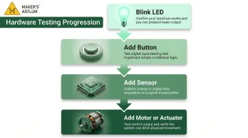
Don't write a complete program before testing any part of it. As Hymel notes, serial logging and toggling a GPIO cover 90% of debugging needs.
Frequently Asked Questions
What programming language is used in microcontrollers?
C and C++ are the most widely used languages due to their low-level hardware access, efficiency, and portability. Python (via MicroPython or CircuitPython) is increasingly popular for beginners and rapid prototyping. Assembly is used for very specific low-level tasks. If you're just starting out, Python or the Arduino variant of C++ is the easiest entry point.
What are the programming methods of microcontrollers?
Three main methods exist: writing code in C/C++ or Python and uploading via an IDE; using a hardware programmer (such as JTAG or ISP interfaces); or flashing via a bootloader (like Arduino's USB bootloader) for simpler setups. The right method depends on your microcontroller family and tools.
How does a microcontroller execute a program?
When powered on, the microcontroller's CPU fetches instructions from flash/ROM memory, decodes each one, and executes them sequentially. The program typically runs in a continuous loop, responding to inputs and controlling outputs indefinitely.
Where is the program stored in a microcontroller?
The compiled program (firmware) is stored in non-volatile flash memory (or ROM/EEPROM in older chips), which retains its contents even when power is removed. Temporary data generated at runtime is stored in RAM, which is cleared on power-off.
What are the basics of microcontrollers?
A microcontroller combines a CPU, flash memory, RAM, and I/O peripherals (GPIO, timers, ADC, and communication interfaces like UART, I2C, and SPI) on a single chip. Together, these let it read inputs, run logic, and control outputs without any external components.
What is an example of a microcontroller?
Common examples include:
- Arduino Uno — uses the ATmega328P (AVR family); ideal for beginners
- ESP32 — popular for IoT projects with built-in Wi-Fi and Bluetooth
- STM32F4 — used in industrial and professional embedded applications
- PIC16F series — widely found in commercial electronics
Each varies in cost, capability, and intended use case.